This is the second blog post on the subject of constitutive modeling. In the first post we investigated the von Mises model and how this is implemented. However, we had our focus on the stress update, i.e. if a new strain state is given, what will the new stress state be. In this post we will look closer on how this model fits into the finite element framework and what modifications are needed compared to linear elasticity.
Mr Elastic?
The subject of constitutive modelling is of course a huge one. So we will need to start somewhere and here we will focus on the numerical implementation and how this is done in the context of finite element modelling. Here some fancy index notation will be used from time to time. This is not to make equations look more fancy (even if that sometimes is true), but rather because this is more convenient. There will also be some matrix notation, but it will (hopefully) be clear when this is used. Let's start by stating the weak form for the equation of motion.
\[ \int \rho v_i \ddot{u}_i dV + \int \epsilon^v_{ij} \sigma_{ij} dV = \int v_i t_i dS + \int v_i b_i dV\]
This looks quite fancy and it gets worse, since \(v_i\) here represents an arbitrary weight vector. Furthermore, \( \ddot{u}_i \), \(t_i\) and \(b_i\) are the acceleration, traction vector and body forces respectively. The term \( \epsilon^v_{ij} \) is a quantity that has a similar definition as the strain tensor. The task is now to get to the finite element formulation and here matrix notation can be helpful. The weak form given above can now be written as:
\[ \int \rho {\bf v}^T \ddot{{\bf u}} dV + \int {\bf \epsilon}^{vT} {\bf \sigma} dV = \int {\bf v}^T {\bf t} dS + \int {\bf v}^T {\bf b} dV \]
Nice, this does not look too bad. The concept of finite element method is that the displacement can be expressed in an approximative manner as
\[ {\bf u} = {\bf N a} \]where \( {\bf N} \) here is called the global shape functions and \( {\bf a} \) is a vector containing the nodal displacements. Furthermore, it is assumed that the shape function is only a function of position and the \( {\bf a} \) is only a function of time, it is possible to get an approximation for the strain according to
\[ {\bf \epsilon} = {\bf B a} \]
where \({\bf B}\) is constructed from \({\bf N}\). We will not look into the shape functions in detail in this blog post. If you would like to know more on this exciting topic, Ottosen and Petersson (1992) is a great book to start with. Now let's put all of this together and see what comes out. In addition, for simplicity, let's assume that no inertia forces are present. Oh, and one more thing: The arbitrary vector \( v \) is chosen according to Galerkin's method. This will give the following:
\[ \int {\bf B}^T {\bf \sigma} dV - { \bf f}_{ext} = { \bf 0 } \]
where
\[ {\bf f}_{ext} = \int {\bf N}^T {\bf t} dS + \int {\bf N}^T {\bf b} dV \]
OK, the above relation does not look too bad. To get any further, the magic of constitutive modelling is needed, i.e. the relation between stress and strain. To make this as simple as possible, let’s use what is called isotropic linear elasticity. Since we are using elasticity, a one to one relationship between stress and strain exists. Also, since it is linear, this is trivial to solve. We have:
\[ {\bf \sigma} = {\bf D \epsilon} = {\bf D B a} \]
Now we have after a lot of text ended up with what many of you have seen before:
\[ {\bf Ka} = {\bf f}_{ext} \]
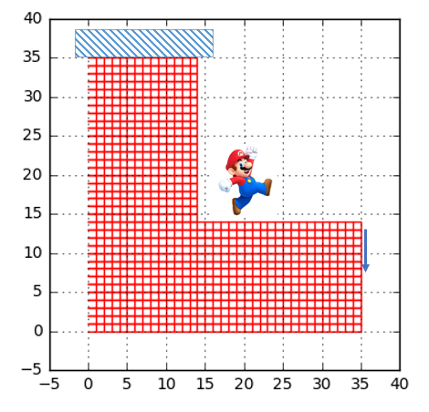
where \[ {\bf K} = \int {\bf B}^T{\bf DB} dV \]Sweet! Now let’s have a look at what some code to solve this problem can look like. We will revisit an old geometry that was investigated in this post. Geometry, loads and boundary conditions can be seen here.

The main part of the code is fortunately very short. The main objective is to assemble the stiffness contribution from every element into one mega stiffness matrix. Since the boundary condition and loads are known, the only thing that is left is to solve the system. The code can be seen below. Here some help has been used of CALFEM for python.
# Create empty stiffnes matrix
K = np.mat(np.zeros((ndof,ndof)))
Area_vec = []

# Set up and solve problem
for i in range(nelm):
    ke = co.plani4e(ex[i],ey[i],ep,D)
    K =  co.assem(Edof[i,1:],K,ke[0])

(a,r) = co.solveq(K,f,bc[:,0])
Ed = co.extractEldisp(Edof[:,1:],a)
The geometry after applying the load can be seen in the figure below. Note that a scale factor has been used for better visualisation of the deformation.
Nice. Now we have some theory and some code to further develop.
Life in plastic, it's fantastic
OK, the case of linear elasticity was pretty intuitive to understand and now we also have some code to build on. So one relevant question will be:
What if the response instead will be nonlinear and plastic? What modifications to the code needs to be done?
We have already in the first blog post investigated what caracterize plasticity. We also show an alternative formulation of the relation between stress and strain. This was done by formulate how the change in strain relates to the change of stress. Also some additional variables are needed (currently unknown how many) to in some way keep track of the loading history.
\[ \dot{\sigma}_{ij} = \dot{\sigma}_{ij}(\dot{\epsilon}_{ij},\kappa) \]
This can also be written in the form
\[ \dot{{ \bf \sigma}} = {\bf D}_t \dot{{ \bf \epsilon}} \]
Here the term \( {\bf D}_t \) is the elastic constitutive matrix if the response is elastic and somthing else yet to be defined if the response is plastic.
Given that we now have this view of the constitutive law, let’s have a closer look at how to solve this kind of problem.
Nonlinear problems...
When solving nonlinear problems, most of you have heard of Newton's method. This method has a “simple” graphical representation when solving problems in one dimension, but of course, the method works fine also for problems in multiple dimensions.
What would happen if we would apply Newton’s method to this kind of problem? First lest state the problem to solve:
\[ {\bf\Psi(a)} = \int {\bf B}^T {\bf \sigma} dV - { \bf f}_{ext} = { \bf 0 } \]
Assume that the external loading is known and fixed and that the stress depends on the displacements. Also assume that the approximation \( {\bf a}^{i-1} \) to the true solution \( {\bf a} \) has been established, where \( i \) here denotes the state of iteration. Ignoring higher-order terms, a Taylor expantion of \( {\bf \Psi} \) at \( {\bf a}^{i-1} \) can be written as:
\[ {\bf\Psi(a)}^{i} = {\bf\Psi(a)}^{i-1} + (\frac{\partial {\bf \Psi}}{\partial {\bf a}})^{i-1} ( {\bf a}^i - {\bf a}^{i-1} ) = {\bf 0} \]
Most of the terms here are known, but one needs some more care.
\[ \frac{\partial {\bf \Psi}}{\partial {\bf a}} = \int {\bf B}^T \frac{ \partial {\bf \sigma}}{\partial {\bf a}} dV \]
With the previously defined form of constitutive law, the following iteration scheme can be formulated
\[ ({\bf K}_t)^{i-1}({\bf a}^i - {\bf a}^{i-1}) = - {\bf\Psi(a)}^{i-1} \qquad {\bf K}_t= \int {\bf B}^T {\bf D}_t {\bf B} dV \]
Not too bad. It looks like the material tangential stiffness has to be calculated in some way to solve this problem. Before proceeding into a more detailed strategy on how to use the above Newton scheme, let’s have a look at a graphical interpretation of it.
Starting from a known state (here marked as \( n \)) a new load step is taken and the applied external force is now \( f_{n+1} \). Moving in the direction of the tangent, the displacement for the next iteration (here represented by \(a^1 \)) can be found. However, when investigating the out-of-balance forces, it is discovered that these are too far from zero to be accepted. The process is then repeated and a new state of iteration can be found (here marked by \( a^2\)). In this state, the out-of-balance forces have been significantly reduced. This process continues until a reasonable low value of the out-of-balance forces has been achieved.
So for every iteration where the external applied external force is \( f_{n+1} \) the following steps are needed
- Calculate \( \bf{ K }_t \) = \(\int {\bf B}^T {\bf D}^{i-1}_t {\bf B} dV \)
- Calculate \( \bf{a}^i \) from \( ({\bf K}_t)^{i-1}({\bf a}^i - {\bf a}^{i-1}) = { \bf f}_{n+1} - { \bf f}_{int} \)
- Calculate the strain \({\bf \epsilon}^i ={\bf Ba}^i \)
- Determine the new stress \( {\bf \sigma}^i \) by integration of the constitutive equations
- Calculate the internal forces \({\bf f}_{int}\) = \( \int {\bf B}^T {\bf \sigma}^i dV \)
- Determine if additional iteration steps are needed by checking out-of-balance forces
This may look like a lot of work and yes some effort will be needed. However, point number 4 has already been investigated in detail in the previous blog post on this subject. Also, how to solve a system similar to the one in point 2 has been established in the example of linear elasticity above. So what is left to do (beside some coding)? Well, you guessed right, the material tangent stiffness \( \bf{D}_t\) needs to be calculated and this will turn out to be somewhat of a challenge.
Let's go hunting for the tangent stiffness
One of the reasons for using the Newton method for solving a set of equations is the rapid convergence. However, for this to be true, the tangent used in the procedure needs to be the correct one. Otherwise the rapid convergence is lost and even a slight error can set you back quite a bit.
Now, what is the correct tangen? In the previous blog post on this subject we investigated the integration of the constitutive equations and for those who remember, the integration was performed using a numerical algorithm. In order to find the correct tangent, the choice of numerical algorithm has to be taken into account, and therefore the tangential stiffness is sometimes referred to as algorithmic tangential stiffness.
Using the notation from the previous blog post, the stress state after integration of constitutive equations is called state (2). It is from this clear the algorithmic tangent stiffness is defined as:
\[ D^{ATS}_{ijkl} = \frac{\partial \sigma^{(2)}_{ij}}{\partial \epsilon^{(2)}_{kl} } \]
Looking at the previous blog post, the deviatoric stress at state (2) can be written as
\[ S^{(2)}_{ij} = (1-3G \frac{\Delta \lambda}{\sigma^{t}_{eff}})S^{t}_{ij} \]
In addition, the trial state of the deviatoric stress has the following expression (along with a short reminder of the definition of the deviatoric strain)
\[ S^{t}_{ij} = S^{1}_{ij} +2G(e^{(2)}_{ij} - e^{(1)}_{ij}) \qquad e_{ij} = \epsilon_{ij} - \frac{1}{3}\epsilon_{kk}\delta_{ij} \]
Since we are investigating von Mises model with linear isotropic hardening, recall that the expression for \( \Delta\lambda \) can be found in explicit form.
\[ \Delta \lambda = \frac{\sigma^{t}_{eff} - \sigma^{(1)}_y}{3G +H} \]
Moreover, the hydrostatic part of the stress is not influenced by plasticity, i.e.
\[ \sigma^{(2)}_{kk} = 3K\epsilon^{(2)}_{kk} \]
Now I am starting to get somewhat tired of writing equations, but the hardest part is yet to come. Mashing the expression for deviatoric stress together with the expression for \( \Delta \lambda \) will give the following expression.
\[ S^{(2)}_{ij} = \frac{H+3G\beta}{H+3G}S^{t}_{ij} \qquad \beta = \frac{\sigma^{(1)}_y}{\sigma^{t}_{eff}} \]
Now let's start to dig into the hard part. From the definition above, \( D^{ATS}_{ijkl} \) can be calculated using the chain rule.
\[ D^{ATS}_{ijkl} = \frac{\partial S^{(2)}_{ij}}{\partial \beta}\frac{\partial \beta}{\partial \epsilon^{(2)}_{kl}} + \frac{ \partial S^{(2)}_{ij}}{\partial S^{(t)}_{mn} }\frac{\partial S^{(t)}_{mn} }{\partial \epsilon^{(2)}_{kl}} + \frac{1}{3}\frac{\partial \sigma^{(2)}_{mm}}{\partial \epsilon^{(2)}_{kl}}\delta_{ij} \]
These expressions above require a good amount of patience and strong coffee. After some grinding, the following expression can be found.
\[ D^{ATS}_{ijkl} = K_1(\frac{1}{2}(\delta_{ik}\delta_{jl} + \delta_{il}\delta_{jk})-\frac{1}{3}\delta_{ij}\delta_{kl})+K\delta_{ij}\delta_{kl} - K_2\frac{S^t_{ij} S^t_{kl}}{ (\sigma^t_{eff})^2 } \]
where the parameters \(K_1\) and \(K_2\) are defined as
\[ K_1 = \frac{H+3G\beta}{H+3G}2G \qquad K_2 = \frac{9G^2\beta}{H+3G} \]
Sweet! Let’s hope that this was worth the effort and the convergence will be fast. Now it is time to write some code.
Time to write some code!
In this coding section of the post, the first thing we need to do is to modify the stress update code from the last blog post. The modification is to add the computation of the algorithmic tangential stiffness. Here the entire code for this function can be found
def stress_update_VM(strain,Hist_old,matpar):

    # Material parameters
    E = matpar[0]
    v = matpar[1]
    sy0 = matpar[2]
    H = matpar[3]
    ptype = matpar[4]

    G = E/(2.0*(1.0+v))

    # Initiate old variables
    ep_o = Hist_old[0:4]
    ep_eff_o = Hist_old[4]

    # Define strain vector
    et = np.array([strain[0],strain[1],0.0,strain[2]/2.0])

    # Compute deviatoric part
    tr_et = et[0] + et[1] + et[2]
    eet_dev = et - 1.0/3.0*tr_et*np.array([1.0,1.0,1.0,0.0]) - ep_o

    # Compute trail stress
    St = 2.0*G*eet_dev

    # Compute value of yield function
    SS_t = St[0]**2 + St[1]**2 + St[2]**2 + 2.0*St[3]**2
    sy_t = sy0 + H*ep_eff_o
    sy_eff_t = np.sqrt(3.0/2.0*SS_t)
    f_t=sy_eff_t-sy_t

    # Elasticity
    if (f_t < 0):
        Hist_new = np.array([ep_o[0],ep_o[1],ep_o[2],ep_o[3],ep_eff_o])
        D_ATS = co.hooke(2,E,v)
        D_ATS = np.delete(D_ATS,2,0)
        D_ATS = np.delete(D_ATS,2,1)

        tr_es=2.0*G*(1.0+3.0*v/(1.0-2.0*v))*tr_et
        es = St + 1.0/3.0*tr_es*np.array([1.0,1.0,1.0,0.0])
        sy = sy_t
        State = 'Elastic'

    # Plasticity
    else:

        # Compute delta lambda
        dl = f_t/(3.0*G + H)

        # Update variables
        ep_n = ep_o + dl*St/sy_eff_t*3.0/2.0
        ep_eff_n = ep_eff_o + dl
        sy = sy0 + H*ep_eff_n

        # Compute new elastic strain
        ee_n=et-ep_n
        tr_een = ee_n[0]+ee_n[1]+ee_n[2]

        S = sy/sy_eff_t*St
        #S = St*(1.0-3*G*dl/sy_eff_t)
        tr_es=2.0*G*(1.0+3.0*v/(1.0-2.0*v))*tr_een
        es = S + 1.0/3.0*tr_es*np.array([1.0,1.0,1.0,0.0])

        # Compute ATS
        K = E/(3.0*(1.0-2.0*v))
        Beta = sy_t/sy_eff_t
        K1 = (H + 3.0*G*Beta)/(H + 3.0*G)*2.0*G
        K2 = 9.0*G**2*Beta/(H + 3.0*G)

        D1111 = 2.0/3.0*K1 + K - K2*(St[0]/sy_eff_t)**2
        D1122 = -1.0/3.0*K1 + K - K2*St[0]*St[1]/(sy_eff_t**2)
        D1112 = -K2*St[0]*St[3]/(sy_eff_t**2)
        D2222 = 2.0/3.0*K1 + K - K2*(St[1]/sy_eff_t)**2
        D2212 = -K2*St[1]*St[3]/(sy_eff_t**2)
        D1212 = 1.0/2.0*K1 - K2*(St[3]/sy_eff_t)**2

        D_ATS = np.matrix([[D1111,D1122,D1112],
                           [D1122,D2222,D2212],
                           [D1112,D2212,D1212]])

        # Update history variabels
        Hist_new = np.array([ep_n[0],ep_n[1],ep_n[2],ep_n[3],ep_eff_n])


    # Return stuff
    return es, D_ATS, Hist_new
Now after this update has been done, the next step is to implement the Newton iteration scheme described previously. The code can be seen below. Note that the geometry definition will not be included in the code.
# Set up and solve problem
for i in range(nelm):
    ke = plani4e(ex[i],ey[i],ep,D_ATS)
    K0 = co.assem(Edof[i,1:],K0,ke)

# Loop over loadsteps
for j in range(loadstep):
    iter = 0
    residual = 10.0
    print('== START LOADSTEP: '+ str(j)+ ' ==')
    f = f + f0

    while residual > 1e-4:
        iter +=1

        (du,r) = co.solveq(K0,f-f_int,bc[:,0])
        u = u + du
        Ed = co.extractEldisp(Edof[:,1:],u)

        # Reset stiffness and internal forces
        K0 = np.mat(np.zeros((ndof,ndof)))
        f_int = np.mat(np.zeros((ndof,1)))

        # Loop over elements
        for i in range(nelm):
            # Compute strain
            strain = plani4s(ex[i],ey[i],ep,Ed[i])

            # Compute Stress
            for kk in range(ir*ir):
                temp_hist = copy.deepcopy(Hist_old[i,:,kk])
                Stress[:,kk],D_ATS[:,:,kk],Hist_new[i,:,kk] = stress_update_VM(strain[:,kk],temp_hist,matpar)

            # Compute internal forces and element stiffnes
            f_e = plani4f(ex[i],ey[i],ep,Stress[[0,1,3],:])
            ke = plani4e(ex[i],ey[i],ep,D_ATS)

            # Assemble force vector
            K0,f_int = co.assem(Edof[i,1:],K0,ke,f_int,f_e.T)

        # Get residual
        f_int[bc[:,0]-1] = 0.0
        residual = np.linalg.norm(f_int-f)
        print('Iter: '+ str(iter) + '\tResidual: ' + str(residual))
    Hist_old = copy.deepcopy(Hist_new)
That was quite a lot of code. Now it is time to test it out on the same geometry as above, but this time we will be prepared to also handle plasticity. A lot of hard work has been put into this code so let’s hope for some good results.
Show me some results!
Let’s start by defining some material parameters. The used parameters can be found below.
| Material properie | Value |
|---|---|
| \( E \) | 210e3 |
| \( \nu \) | 0.3 |
| \( \sigma_{y0} \) | 250 |
| \( H \) | \(0.05*E\) |
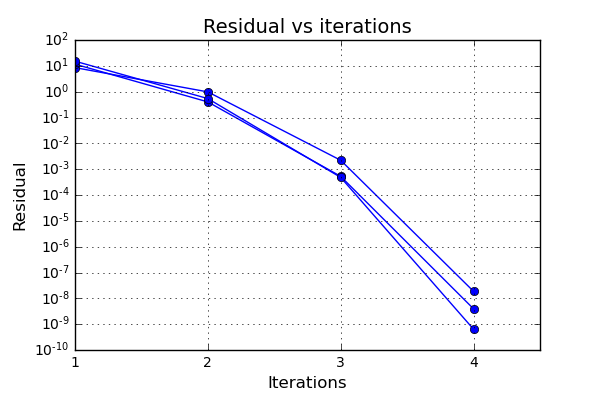
And now it is time to actually run the code. Here 30 load steps will be used where the external load is increased uniformly for every load step. During the execution of the code, the residual is monitored in order to evaluate the quality of the implementation of the algorithmic tangential stiffness. Let’s have a look at some typical residuals and how the residuals are reduced during the iterations. The graph below shows some examples.

This actually looks really nice! The Newton method is known for having a quadratic convergence, and as can be seen especially between the third and fourth iteration, this is achieved.
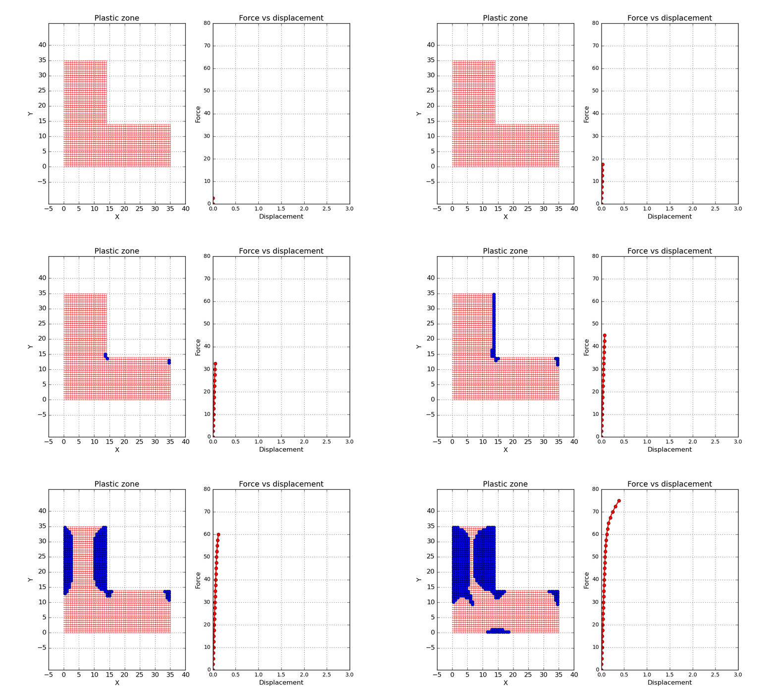
Now let’s have a look at the results. One interesting property to investigate is the size of the plastic zone during the load steps. Below a short animation can be seen where the plastic zone is marked by blue dots. Here a simplified approach has been used to evaluate the plastic zone. If one gauss point has reached plasticity, the entire element is marked as a plastic zone. In addition a force vs displacement curve is shown, where one of the loaded nodes is tracked.

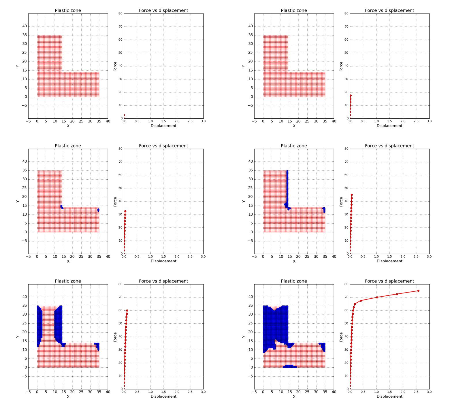
One final thing before wrapping up this post. Let’s conduct a second simulation but this time let’s reduce the hardening parameter to a value close to zero. Since the material is not able to increase the load carrying capacity after reaching plasticity, it is expected that something close to a plastic hinge will be formed when the load gets high enough. Let’s try it out and see what happens.

Well, not to bad! A dramatic increase of the displacement can bee seen by the end of the simulation.
Time to conclude
In this second post on the subject of constitutive modelling and implementation, we have looked at how a plasticity model is incorporated into a finite element solver. When a Newton algorithm is used, the need for a correct tangent stiffness is crucial for the performance. The code has been tested on a “simple” geometry with a good rate of convergence.
Well, that's all for this time. Hopefully this was not the final post on this very exciting subject. And as always, please feel free to reach out to us on info@gemello.se.
Reference
The Mechanics of Constitutive Modeling. / Ottosen, Niels Saabye; Ristinmaa, Matti. Elsevier, 2005. 745 p
Introduction Finite Element Method / Ottosen, Niels Saabye; Petersson, Hans. Pearson, 1992. 432 p